
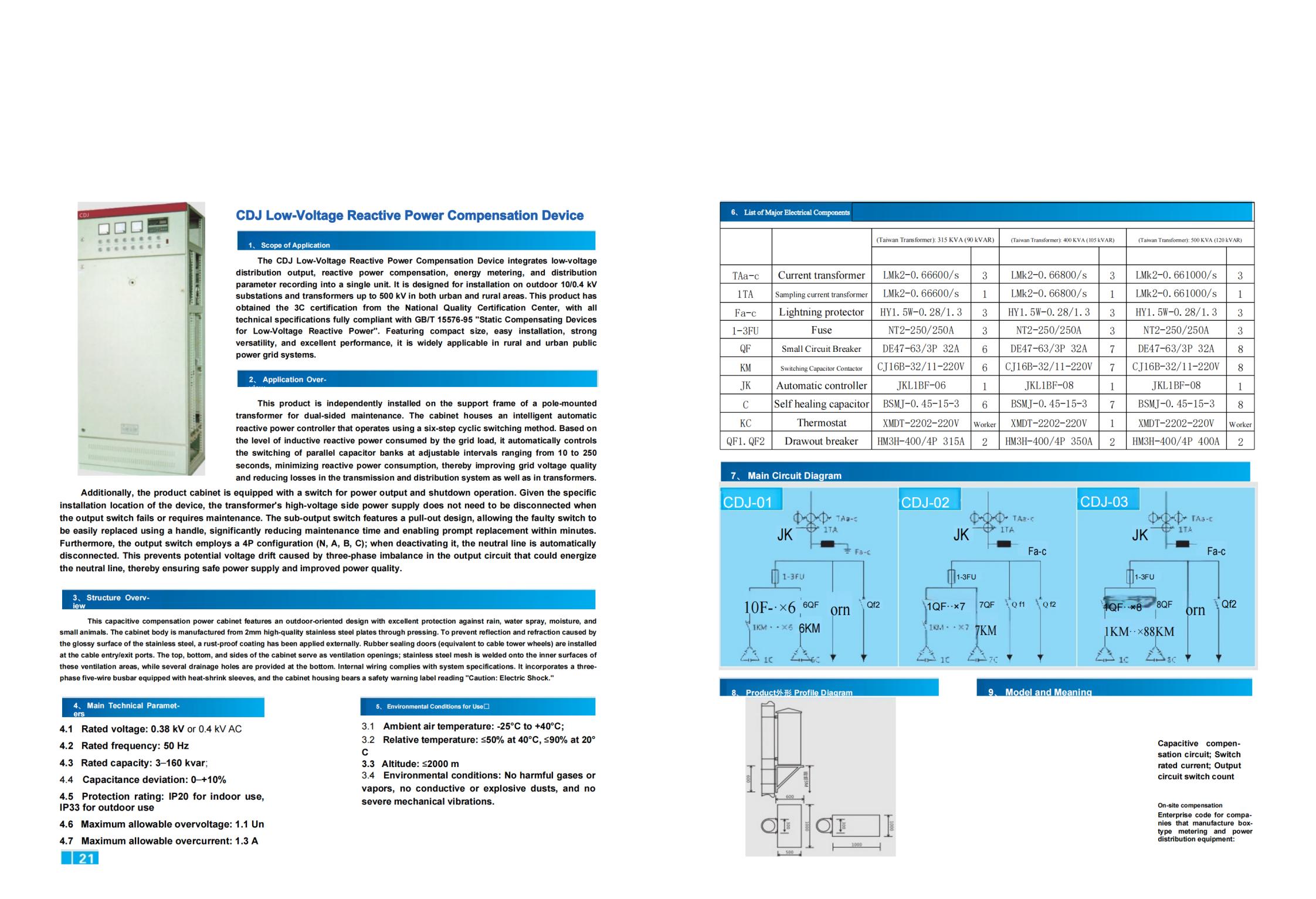
CDJ Low-Voltage Reactive Power Compensation Device | Product Overview
1. Scope of Application
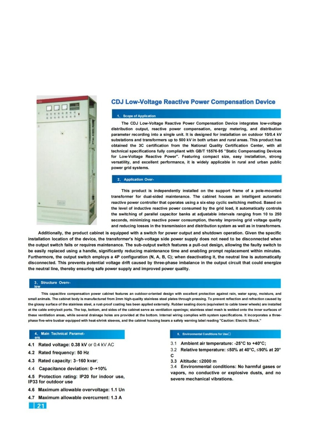
The CDJ Low-Voltage Reactive Power Compensation Device integrates low-voltage distribution output, reactive power compensation, energy metering, and distribution parameter recording into a single, compact unit. It is specifically designed for installation on outdoor 10/0.4 kV substations and pole-mounted transformers rated up to 500 kVA in both urban and rural power grids.
This product has obtained 3C certification from the China National Quality Certification Center, and its technical specifications fully comply with the national standard GB/T 15576-95 “Static Compensating Devices for Low-Voltage Reactive Power”. Featuring a compact footprint, ease of installation, strong versatility, and outstanding performance, it is widely deployed in public power distribution networks across rural and urban areas.
2. Application Overview
The device is mounted independently on the support frame of a pole-mounted transformer, allowing convenient access for dual-side maintenance. Inside the cabinet, an intelligent automatic reactive power controller operates using a six-step cyclic switching method.
Based on the level of inductive reactive power drawn by the grid load, the controller automatically manages the switching of parallel capacitor banks. The switching interval is adjustable between 10 and 250 seconds, effectively minimizing reactive power consumption. This improves grid voltage quality and reduces power losses in both the transmission/distribution system and the transformer.
Additionally, the cabinet is equipped with switches for power output and shutdown operations. Due to the specific installation location, the high-voltage side of the transformer does not need to be disconnected when the output switch fails or requires maintenance. The sub-output switch features a pull-out (drawout) design, allowing faulty switches to be quickly replaced using a dedicated handle. This significantly reduces maintenance time, enabling replacement within minutes.
Furthermore, the output switch adopts a 4-pole configuration (N, A, B, C). When deactivated, the neutral line is automatically disconnected. This prevents potential voltage drift caused by three-phase imbalance in the output circuit from energizing the neutral line, thereby ensuring safe power supply and enhanced power quality.
3. Structure Overview
This capacitive compensation power cabinet features an outdoor-oriented design with excellent protection against rain, water spray, moisture ingress, and small animals.
- Cabinet Material: Manufactured from 2 mm high-quality stainless steel plates through a pressing process.
- Surface Treatment: A rust-proof coating is applied externally to prevent light reflection and refraction caused by the glossy stainless steel surface.
- Sealing Protection: Rubber sealing gaskets are installed at all cable entry and exit points.
- Ventilation Design: Ventilation openings are located at the top, bottom, and sides of the cabinet. Stainless steel mesh is welded onto the inner surfaces of these ventilation areas, and multiple drainage holes are provided at the bottom.
- Internal Wiring: All internal wiring complies with system specifications. A three-phase five-wire busbar system is used, equipped with heat-shrink sleeves.
- Safety Warning: A prominent safety label reading “Caution: Electric Shock” is affixed to the cabinet housing.
4. Main Technical Parameters
| Parameter | Specification |
|---|---|
| Rated Voltage | 0.38 kV or 0.4 kV AC |
| Rated Frequency | 50 Hz |
| Rated Capacity | 3 – 160 kvar |
| Capacitance Deviation | 0 – +10% |
| Protection Rating | Indoor: IP20 / Outdoor: IP33 |
| Max. Allowable Overvoltage | 1.1 Un |
| Max. Allowable Overcurrent | 1.3 A |
5. Environmental Conditions for Use
- Ambient Air Temperature: -25°C to +40°C
- Relative Humidity: ≤50% at 40°C; ≤90% at 20°C
- Altitude: ≤2000 m
- Environmental Requirements: No harmful gases or vapors, no conductive or explosive dust, and no severe mechanical vibration.
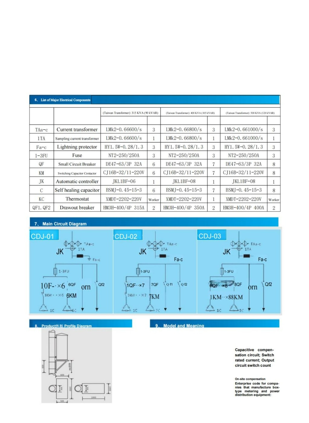
6. List of Major Electrical Components
| Code | Component Name | Model (315KVA / 90kVAR) | Qty | Model (400KVA / 105kVAR) | Qty | Model (500KVA / 120kVAR) | Qty |
|---|---|---|---|---|---|---|---|
| TAa-c | Current Transformer | LMk2-0.66 600/5 | 3 | LMk2-0.66 800/5 | 3 | LMk2-0.66 1000/5 | 3 |
| 1TA | Sampling CT | LMk2-0.66 600/5 | 1 | LMk2-0.66 800/5 | 1 | LMk2-0.66 1000/5 | 1 |
| Fa-c | Surge Arrester | HY1.5W-0.28/1.3 | 3 | HY1.5W-0.28/1.3 | 3 | HY1.5W-0.28/1.3 | 3 |
| 1-3FU | Fuse | NT2-250/250A | 3 | NT2-250/250A | 3 | NT2-250/250A | 3 |
| QF | Miniature Circuit Breaker | DE47-63/3P 32A | 6 | DE47-63/3P 32A | 7 | DE47-63/3P 32A | 8 |
| KM | Switching Capacitor Contactor | CJ16B-32/11-220V | 6 | CJ16B-32/11-220V | 7 | CJ16B-32/11-220V | 8 |
| JK | Automatic Controller | JKL1BF-06 | 1 | JKL1BF-08 | 1 | JKL1BF-08 | 1 |
| C | Self-Healing Capacitor | BSMJ-0.45-15-3 | 6 | BSMJ-0.45-15-3 | 7 | BSMJ-0.45-15-3 | 8 |
| KC | Thermostat | XMDT-2202-220V | 1 | XMDT-2202-220V | 1 | XMDT-2202-220V | 1 |
| QF1, QF2 | Drawout Circuit Breaker | HM3H-400/4P 315A | 2 | HM3H-400/4P 350A | 2 | HM3H-400/4P 400A | 2 |
Note: The component configurations above correspond to different transformer capacities. Please select based on actual project requirements.
Our Commitment
We create high-quality products that give our customers complete peace of mind.